Lighter by simulation,
not by guesswork.
A client wanted the lower frame of their multirotor as one carbon fiber plate, as light as it could be. I built the load cases from how it flies, let topology optimization find the load paths, and checked every revision in a plate FE model that was validated against hand calculations first. Then I designed a printed version to compete with it.
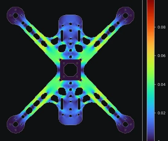 Failure index, plate FE. 1.0 would be first-ply failure
- Part
- Unibody lower base plate for a multirotor
- Replaces
- A three-piece plate and arm stack
- Material
- 4 mm carbon fiber plate, plus a printed CF nylon option
- Load cases
- Motor thrust, roll twist, battery inertia
- Finding
- Stiffness is the limit, not strength
- Status
- Design review with the client
One plate instead of three parts
The problem
The client's multirotor used a lower frame made of two crossing arms and a center plate. Every joint was weight and flex. They wanted one flat plate, cut from carbon fiber sheet, as light as it could be without going soft.
The approach
Trace the original, then lighten it with the loads in the loop. Thrust at each motor, a roll twist through the motor screws and the battery's inertia on landing, with the plate clamped at the flight stack. Topology optimization found the load paths. A plate FE model checked every revision.
The result
A load-path trellis about 20 g lighter than the solid traced plate, roughly twice as stiff as the first skeleton cut, and a finding the client could act on at the cutter: run the weave along the arms and the stiffness roughly doubles.
Client work, shared with permission and without the client name, product name or part dimensions.
Three things that made the numbers worth trusting
Loads from how it flies
Thrust at every motor sized to cover full-throttle spikes and a hard landing, a roll couple through the motor screws, and the battery pulling on the body. Not a single generic pressure.
Topology optimization with three cases
The optimizer had to satisfy thrust, twist and battery inertia at once. It kept the arms solid near the root, where bending is highest, and opened up the low-load body and corners.
Validated models, not pretty pictures
The orthotropic plate model was checked against a hand calc within 2 percent. The 3D model for the printed version was checked against beam calcs within 3 percent and against the plate model.
Four revisions, one plate model
Carbon plate, weave along the arms
| Revision | Mass | Tip deflection | Arm mode | Strength SF |
|---|---|---|---|---|
| Rev 3, traced solid | 92 g | 0.80 mm | 110 Hz | 16 |
| Rev 4, skeleton | 63 g | 2.00 mm | 71 Hz | 5 |
| Rev 5, uniform trellis | 65 g | 2.42 mm | 64 Hz | 4 |
| Rev 6, load-path trellis | 72 g | 1.09 mm | 95 Hz | 13 |
- Rev 4 and 5 were light but floppy. Taking material out evenly is not the same as taking it out where it is not working.
- Rev 6 keeps the arms solid near the root and opens the low-load body. About 2x stiffer than Rev 4 for about 9 g, and 20 g lighter than the solid plate.
- Cutting the blank with the weave square to the arms roughly halves the stiffness on every version. That one call matters more than any cutout.
Tip deflection at the design thrust per motor. Arm mode is the estimated first bending frequency. Material properties are typical published values for woven carbon, not tested.
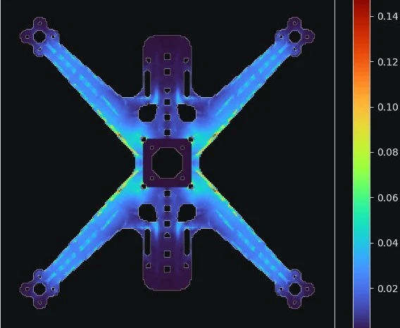
Printed alternative, same load cases
| Version | Mass | Tip | Mode | SF |
|---|---|---|---|---|
| Rev 6 carbon, weave along arms | 72 g | 1.09 mm | 95 Hz | 13 |
| Rev 6 carbon, weave square | 72 g | 2.67 mm | 61 Hz | 5 |
| Printed CF nylon, ribbed | about 73 g | about 0.9 mm | about 105 Hz | about 7 |
A flat printed plate cannot compete with carbon. A ribbed one can. Straight tapered arms aimed at the clamp, ribs hanging below the deck so it prints flat with no supports, and it comes out about 20 percent stiffer than the carbon plate at about the same weight. The trade is more body flex under the battery and a nylon that softens with humidity, so the client gets both options and the reasons.
How it was done
- 01
Trace and clean up
The original scan was traced, de-skewed and mirror-averaged into a clean outline with every mounting hole kept exactly.
- 02
Load cases and clamp
Per-motor thrust, roll twist and battery inertia, with the plate clamped over the flight stack. Tip mass for the motor and prop in the vibration check.
- 03
Plate FE
An orthotropic Mindlin plate model on a 1 mm grid for woven carbon. Checked against a cantilever hand calc before trusting any result.
- 04
Topology optimization
SIMP optimization across all three cases set the trellis layout. Rev 5 proved a uniform rib pattern is the floppiest option. Rev 6 followed the load paths.
- 05
Printed alternative
A ribbed CF nylon version, modeled in 3D voxel FE with quarter symmetry. Ribs hang below the deck so it prints flat with no supports and stays clear of the props.
- 06
Hand it over with findings
STEP, DXF and a one-page load check per revision, plus the weave orientation call and the open items before a flight test.
Open items, stated plainly in the handoff: rerun the loads with the client's final motor, prop and all-up weight, and do a physical flex test before flying. Crash loads and in-plane knocks were out of scope.
What this means for your project
Take the weight out where it is not working.
Brackets, plates, arms and housings. Real load cases, topology optimization and an FE check on every revision, with the model validated before you see a number.
Designed for how it will actually be made.
Weave orientation on a cut plate, rib direction on a print, layer lines in a crash. The handoff tells your cutter or your printer what matters, not just what shape to make.
Got a part that is heavier than it needs to be?
Send me the CAD and what it has to survive. I reply within 2 business days and I will sign your NDA first.
Start a project→