Air to the caliper.
Hung off two bolts.
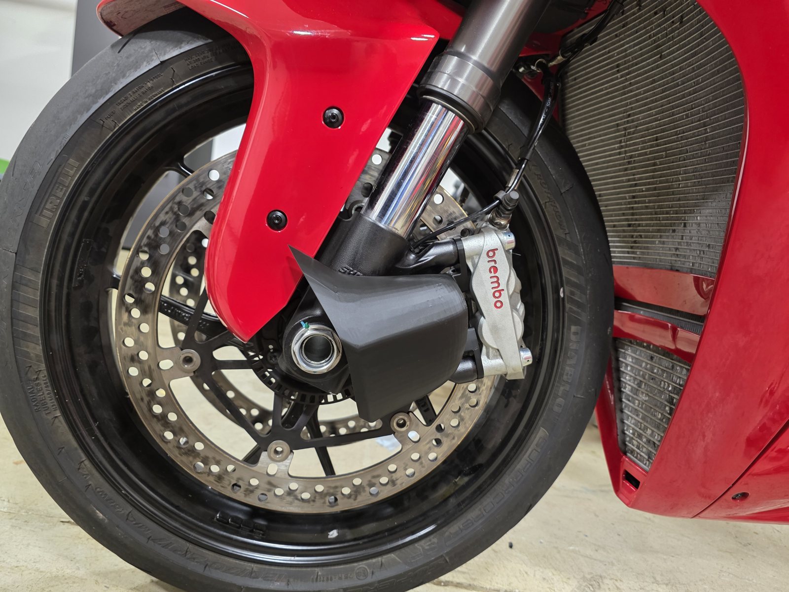
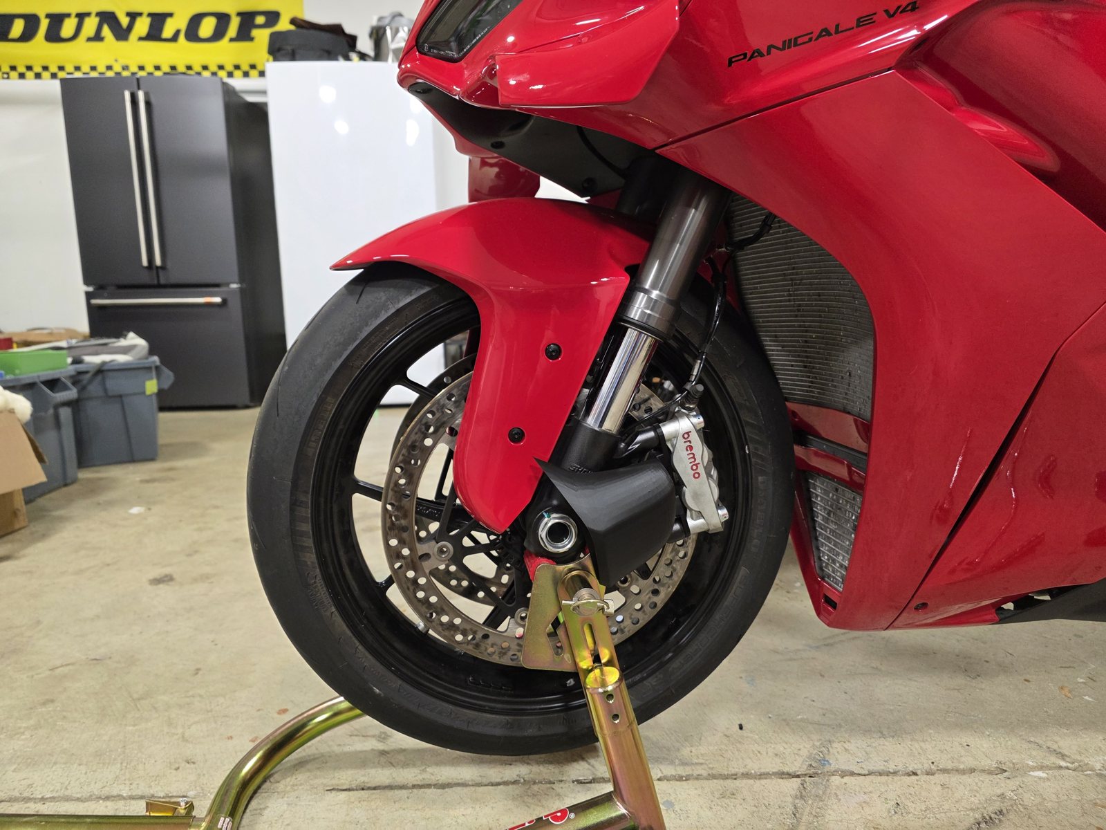
A front brake cooling cowl for my Panigale V4. A scoop beside the axle picks up air and a swept duct carries it back to the caliper. No brackets and no drilling: the cowl clamps under the caliper's own mount bolts. Modeled in Inventor around the real rotor and mount, printed, fit on the bike, then checked with a CFD run.
- Bike
- Ducati Panigale V4
- Brakes
- 330 mm rotor, radial-mount caliper
- Mounting
- Clamps on the two caliper mount bolts
- Parts
- Left cowl plus a mirrored right
- Material
- PA6-GF for the production part
- Status
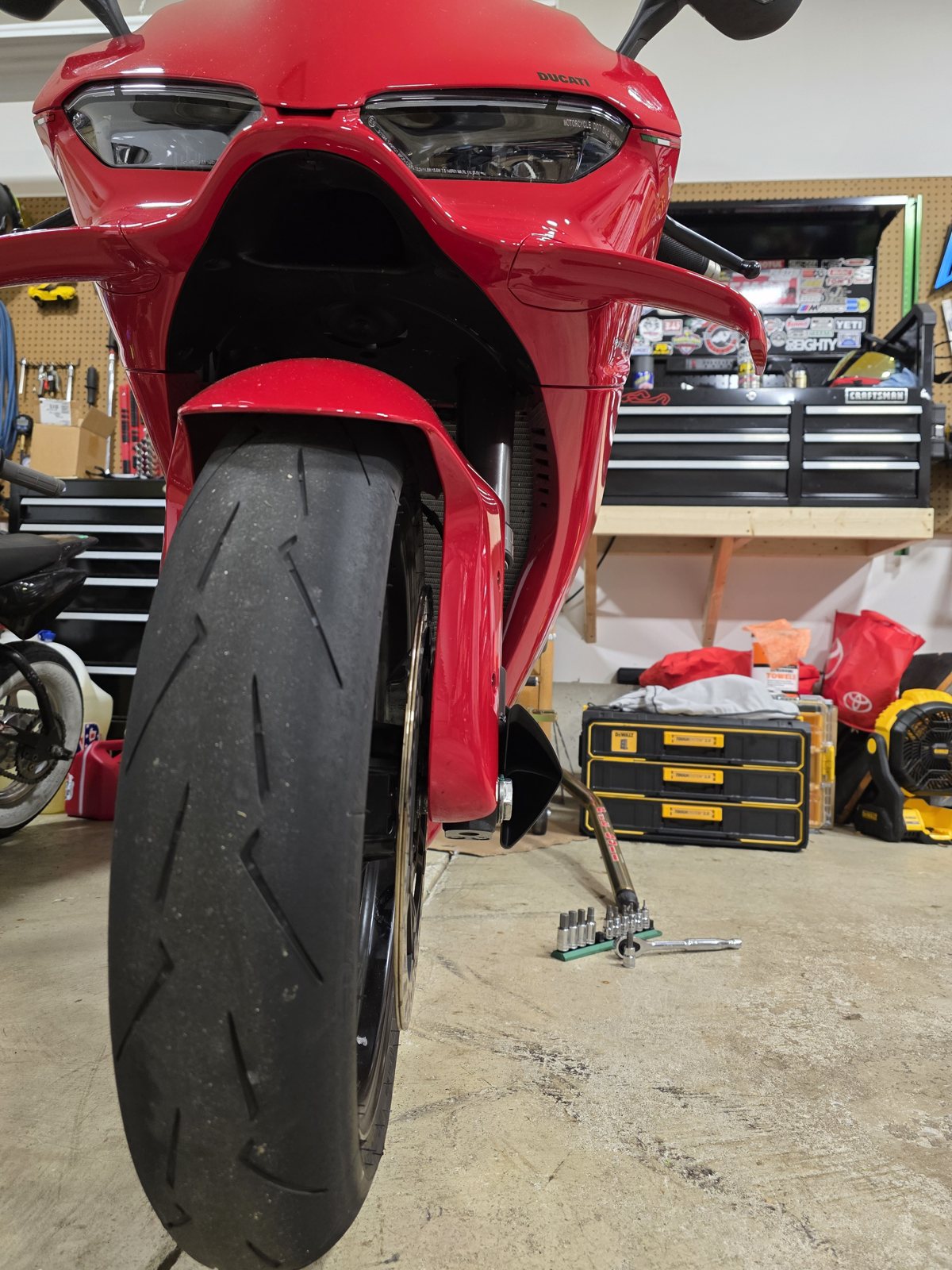
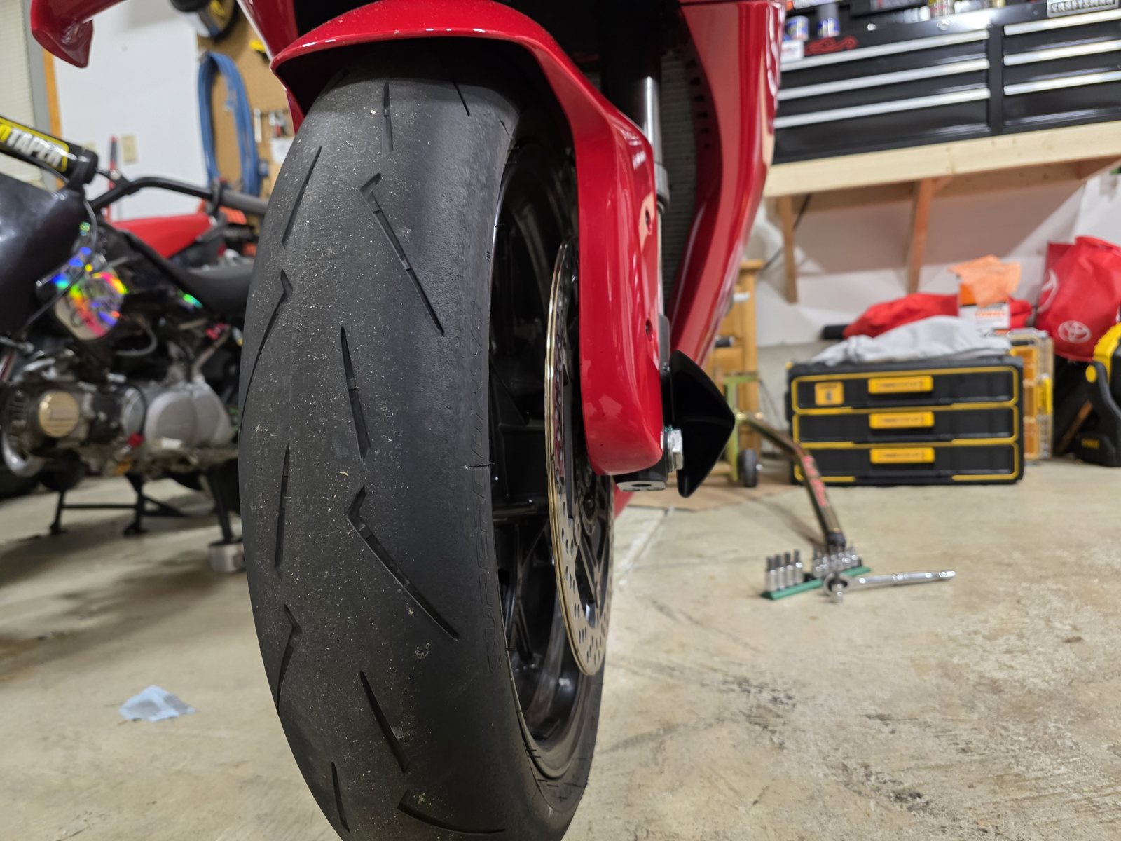
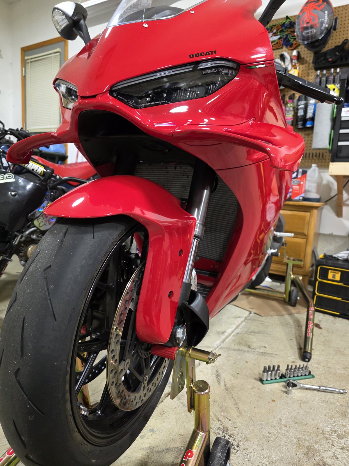
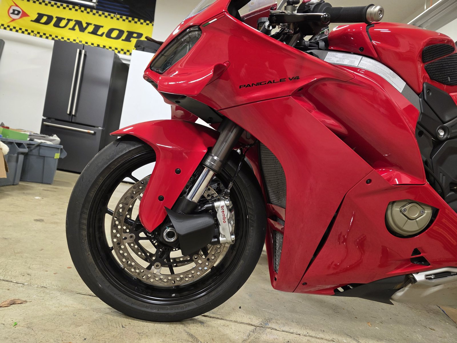
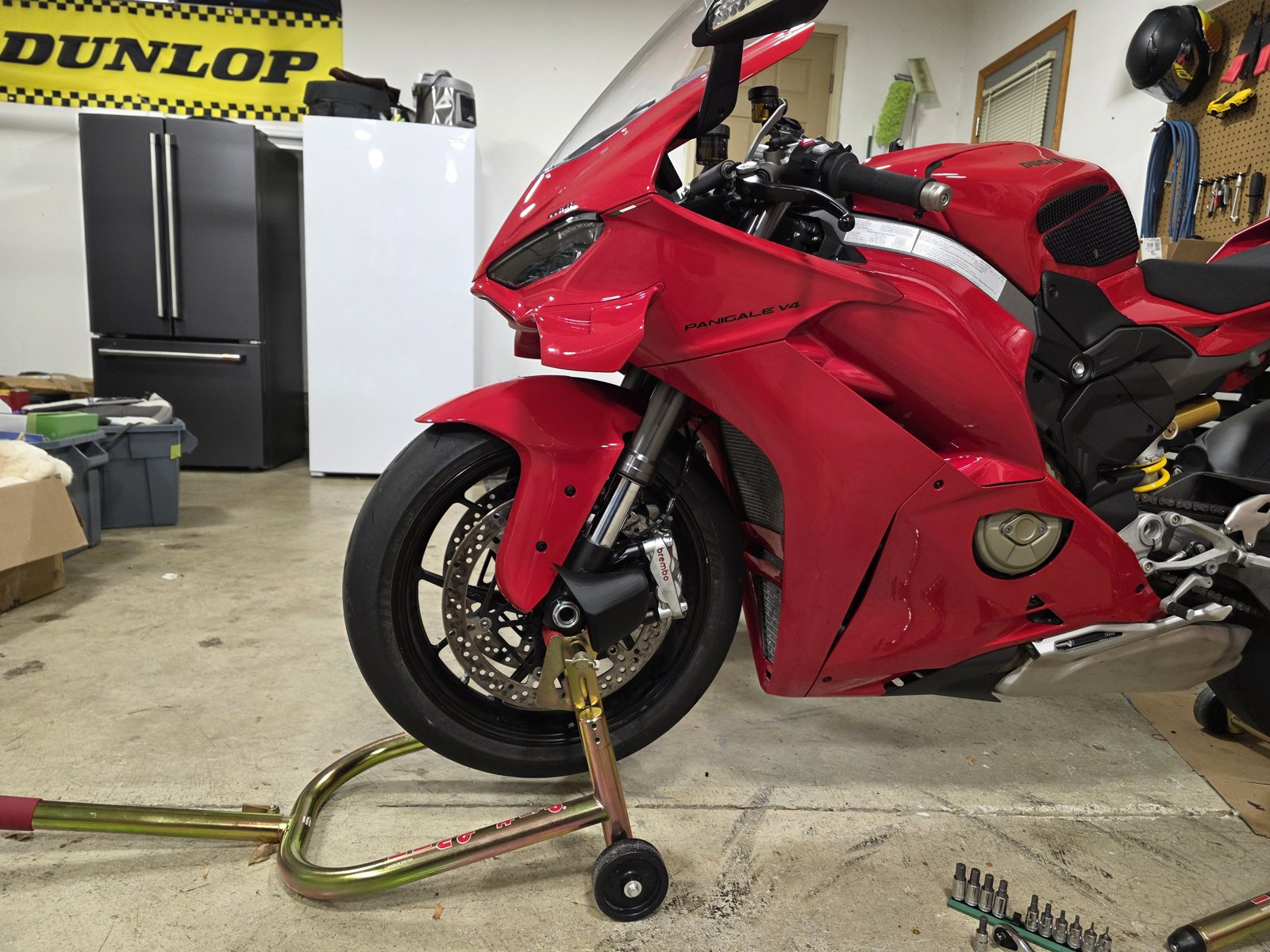
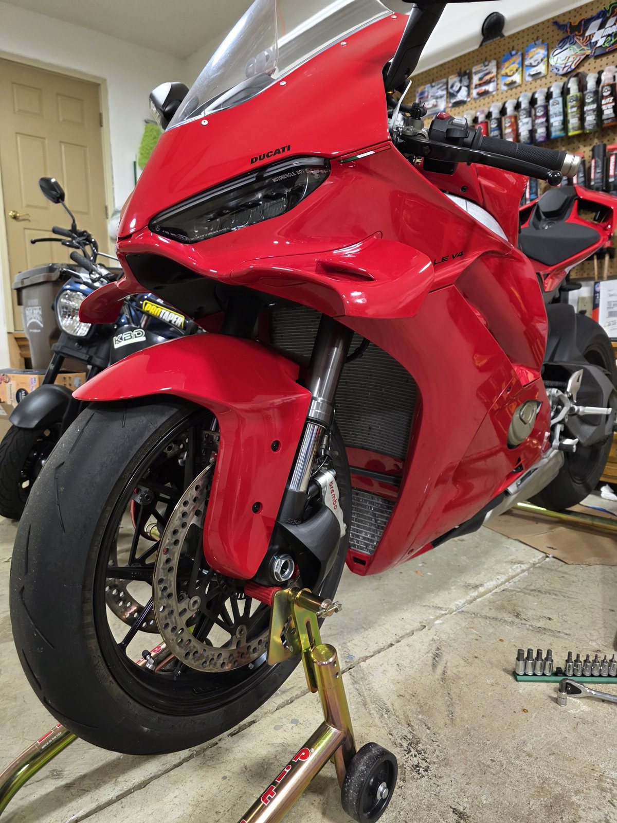
- MK1 printed and test fit on the bike
Why the cowl exists
The challenge
Get air onto the front caliper with nothing new bolted to the fork. The only hardware available is the caliper's two radial mount bolts, and the part has to clear the rotor, the fork foot and the fender.
What I did
I put the rotor, the caliper mount and a fork silhouette into an Inventor assembly first, then modeled the cowl in place: a scoop beside the axle, a duct swept back to the caliper, and ears that sit on the mount bosses. The right side is a mirror of the left.
The result
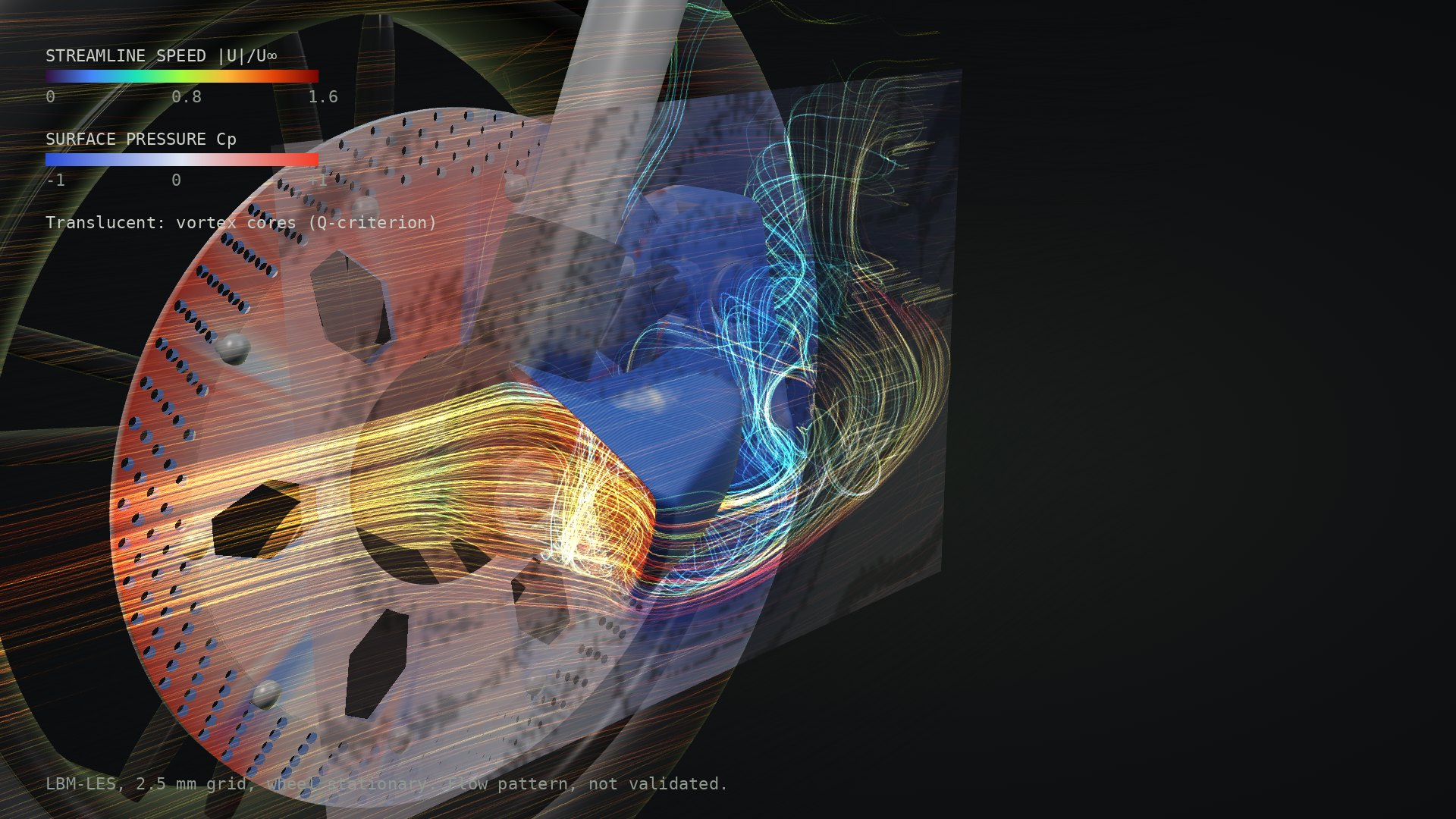
The MK1 print bolts on under the caliper bolts and fits clean against the fender, rotor and fork foot. A CFD run on the assembly shows the duct delivering a jet of air onto the caliper, and where the next revision can pull in more.
Three features that do the work
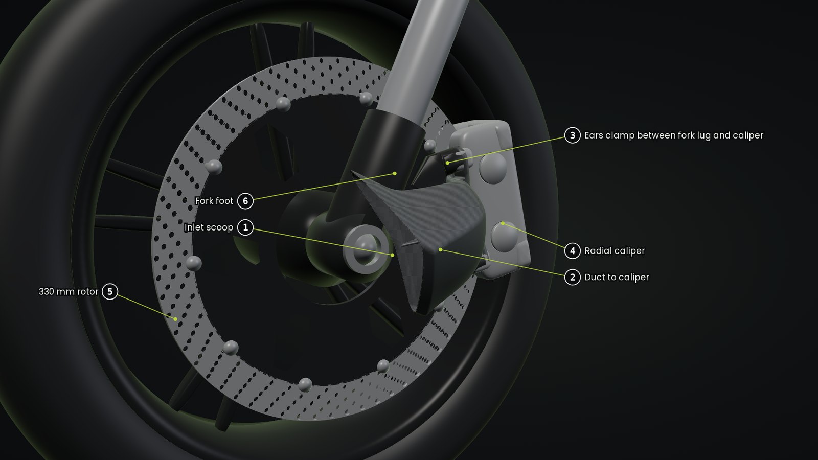
Inlet scoop
A tall slot beside the axle, outboard of the fork foot and under the fender, facing straight into the airstream.
Duct to the caliper
The cowl and the fork foot form the duct together. It sweeps back and inboard and lets the air out at the caliper.
Bolt-on ears
The ears sit on the radial mount bosses and clamp between the fork lugs and the caliper, so the caliper bolts hold the cowl. Nothing new is drilled or bonded.
Where the air actually goes
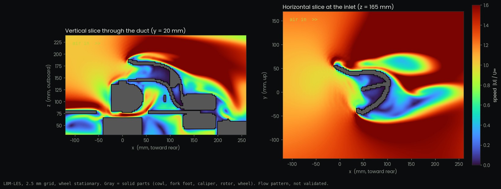
- Inlet speed
- ~1/3 of free stream
- Capture streamlines reaching the caliper
- ~3 in 4
- Jet onto the caliper
- ~0.5x free stream
What the run shows
- ✓Tracing the solved flow backward from the inlet shows the capture streamtube: the air the scoop actually swallows, and the path it takes through the duct to the caliper.
- ✓About three in four of those streamlines reach the caliper. The duct delivers a jet of roughly half free-stream speed onto the outboard side of the caliper.
- ✓Mean speed across the inlet is about a third of free stream. Pressure builds ahead of the mouth (red on the cut plane) and some of the oncoming air spills around the outside of the scoop.
- ✓The outer skin of the cowl and the space behind it sit in suction, which is where the vortex cores in the wake form.
- ✓Next revision: more exit area and a smoother turn into the caliper so the duct can swallow more of what the scoop catches. Next run: rotating wheel and a finer grid around the duct.
How it was run
Lattice-Boltzmann (D3Q19) with a Smagorinsky LES model, 2.5 mm lattice, about 5.2 million cells.
Wheel stationary, no ground plane, no heat, rotor holes not resolved. Caliper is a modeled radial monobloc and the fork is a reference shape. Pressure is referenced to undisturbed air at each station. Good for flow pattern and comparing revisions, not for numbers to design to.
Hardware first, then the part
- 01
Capture
The 330 mm rotor, the radial caliper mount with its two bosses, and a fork silhouette go into the assembly first.
- 02
Model
Cowl modeled in Inventor in place: scoop, swept duct, and ears on the mount bosses. Right side is a mirror.
- 03
Print
MK1 printed as a fit-check prototype, left and right. PA6-GF is the material for the production part.
- 04
Test fit
Bolted on the bike under the caliper bolts. Checked against the fender, the rotor and the fork foot.
- 05
CFD
Coarse flow solve around the assembly to see where the air goes before the next revision.
MK1 on the bike
What this means for your project
Ducts, guards and aero parts that bolt to what you already have.
Send photos and tell me what you want to cool, guard or clean up. I model the part around your hardware, fit check a print on your bike, and can run a quick flow check before you commit to a final part.
The same process, for your product.
Design around existing hardware, printed fit-check prototypes, and early CFD to compare concepts. Then drawings and print or tooling files your vendor can quote.
Got a part that needs air?
Send me photos and what you are trying to cool or package. I review every request myself and reply within 2 business days.
Start a race project→