Same bolts. New shape.
Built for metal printing.
A riding school needed passenger peg extension brackets for their Yamaha MT-10 fleet. I quoted the billet version first. Then they asked what the part would look like designed for 3D printed metal. This is that part: topology optimized, checked in FEA, about 30% lighter, and quoted for production.
- Bike
- Yamaha MT-10, left and right
- Started as
- Pocketed 6061-T6 billet
- Redesigned for
- Metal powder bed printing
- Mass
- About 190 g to about 134 g
- Checked at
- 5 kN, 40 mm outboard
- Status
- Designed, FEA checked, quoted
A quote that turned into a redesign
The challenge
A riding school needed passenger peg extension brackets for their MT-10 fleet. I quoted the billet version first. Then they asked what the part would look like if it was designed for 3D printed metal.
What I did
Kept the bolt pattern and mating faces, opened up everything else, and let topology optimization find the load path. Checked it in FEA every step, then turned it into a clean solid ready for the printer and the shop.
The result
About 30% lighter than the billet part and stiffer in the same load case. Left and right hand parts, with a production quote for printed metal next to the CNC quote so the customer can compare with real numbers.
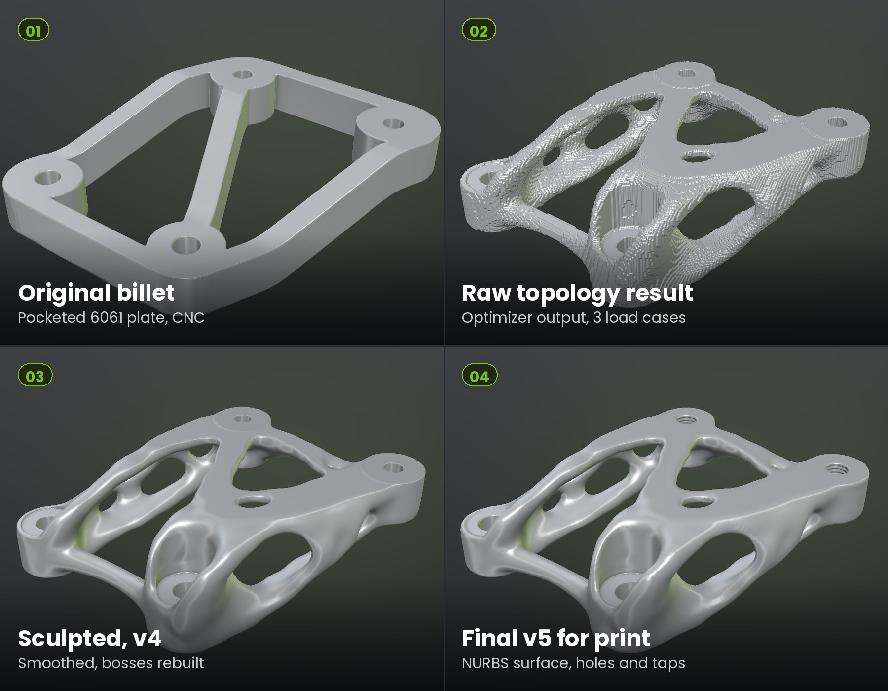
Billet to print-ready in four steps
Four details that matter
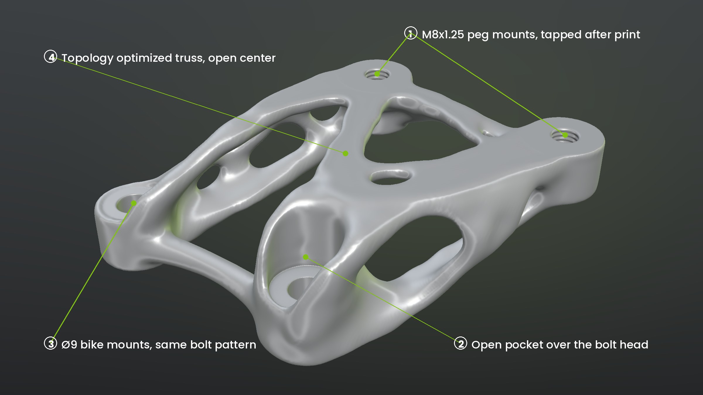
M8 peg mounts
Printed undersize, then drilled and tapped M8x1.25-6H by hand. The top face carries stock so it machines flat and to height.
Open bolt pocket
The rear boss is scooped open over the bolt head instead of a deep counterbore. Same stock bolt, less metal, room for the tool.
Same bolt pattern
Both bike mounts stay exactly where the original part had them, with the same flat face against the bike.
Optimized truss
The material between the mounts came from topology optimization on three load cases. The middle is open where it was not doing any work.
Checked in FEA before anyone melts powder
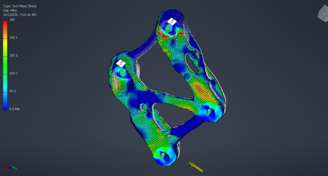
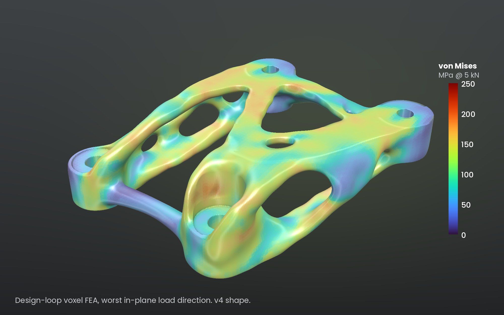
| At 5 kN, 40 mm outboard | Original billet | Printed design |
|---|---|---|
| Mass | about 190 g (6061) | about 134 g (AlSi10Mg) |
| Deflection at the peg mount, 5 kN | 2.3 mm | 0.7 to 0.9 mm |
| Peak stress, 5 kN | about 500 MPa | about 230 MPa |
| Working load at 1.5 safety factor | about 1.3 kN | about 2.9 kN |
Static loads only. The full 5 kN with margin calls for Ti-6Al-4V from the same file, or a proof load before release.
From a CNC quote to a printed metal quote
- 01
Quote
Started with the customer STEP files and drawing for a billet part. Quoted the CNC batch for left and right hand.
- 02
Design space
Locked the bolt pattern and mating faces. Opened the volume to the full depth, thick at the mounts and free in the middle.
- 03
Optimize
Topology optimization on three load cases, then FEA every iteration. Added material where stress peaked, trimmed what carried nothing.
- 04
Sculpt
Smoothed the raw result into a continuous surface and rebuilt it as a clean NURBS solid through a quad cage and T-spline.
- 05
Finish
Holes, taps, machining stock and edge breaks in Inventor. Mirrored for the left side. STEP and IPT for both.
- 06
Quote again
Print orientation, finishing steps and material recommendation into a production quote next to the CNC price.
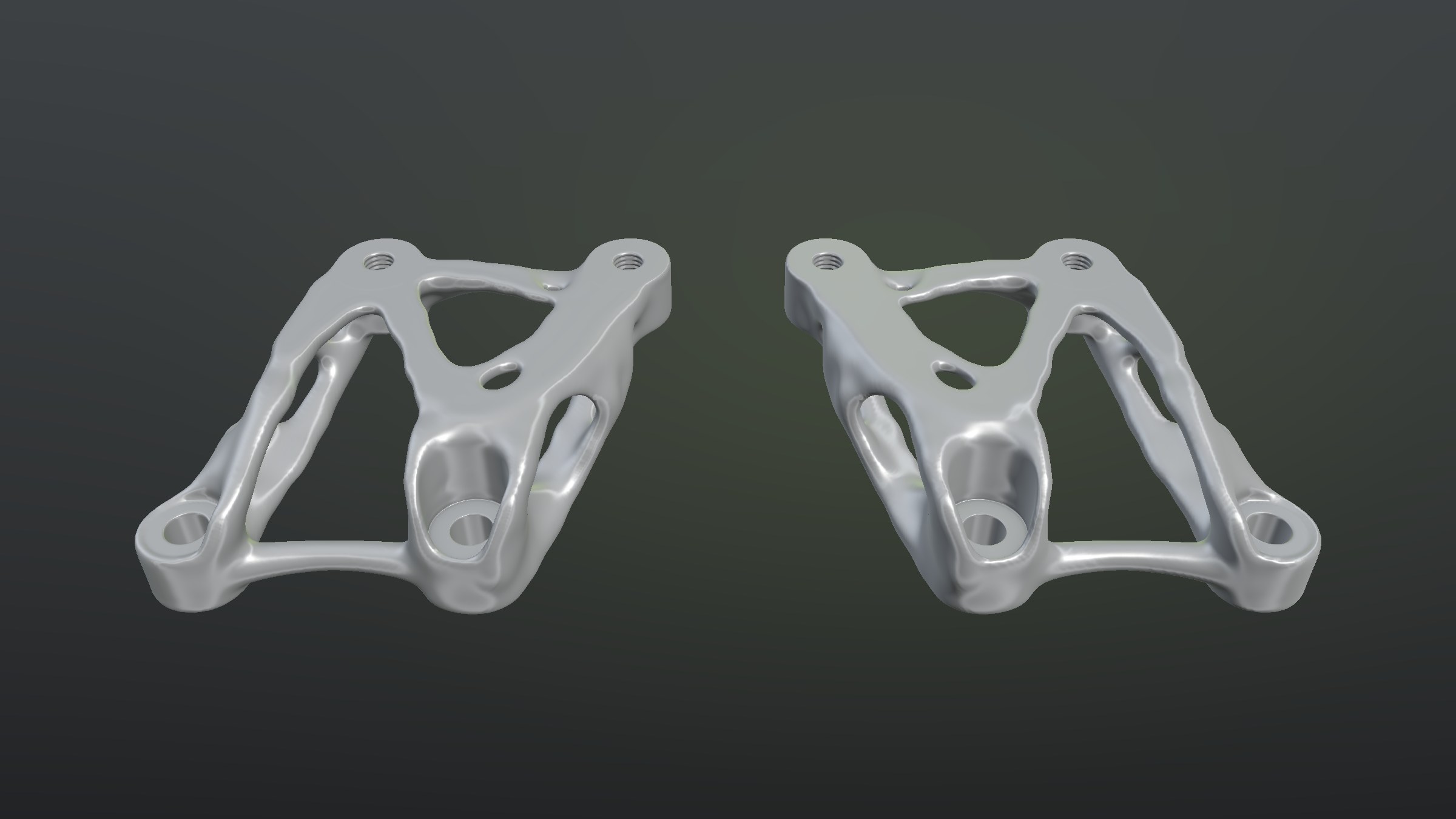
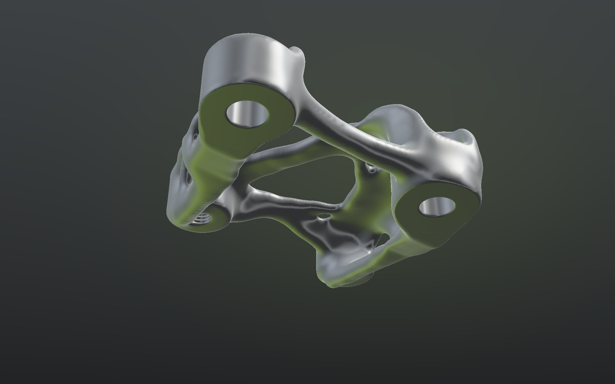
Left, right, and the side you bolt to
What this means for your project
Get it quoted both ways.
Send the STEP and the drawing. I can quote it as drawn for CNC, and show you what it could be as a printed metal part, so you can compare weight, cost and lead time with real numbers.
Design for additive, start to finish.
Load cases, topology optimization, FEA, a clean CAD solid with the machined features, print orientation and finishing steps. You get STEP and native files, not just a mesh.
Got a part that should be lighter or made differently?
Send me the STEP and what it needs to do. I review every request myself and reply within 2 business days.
Send me your part→