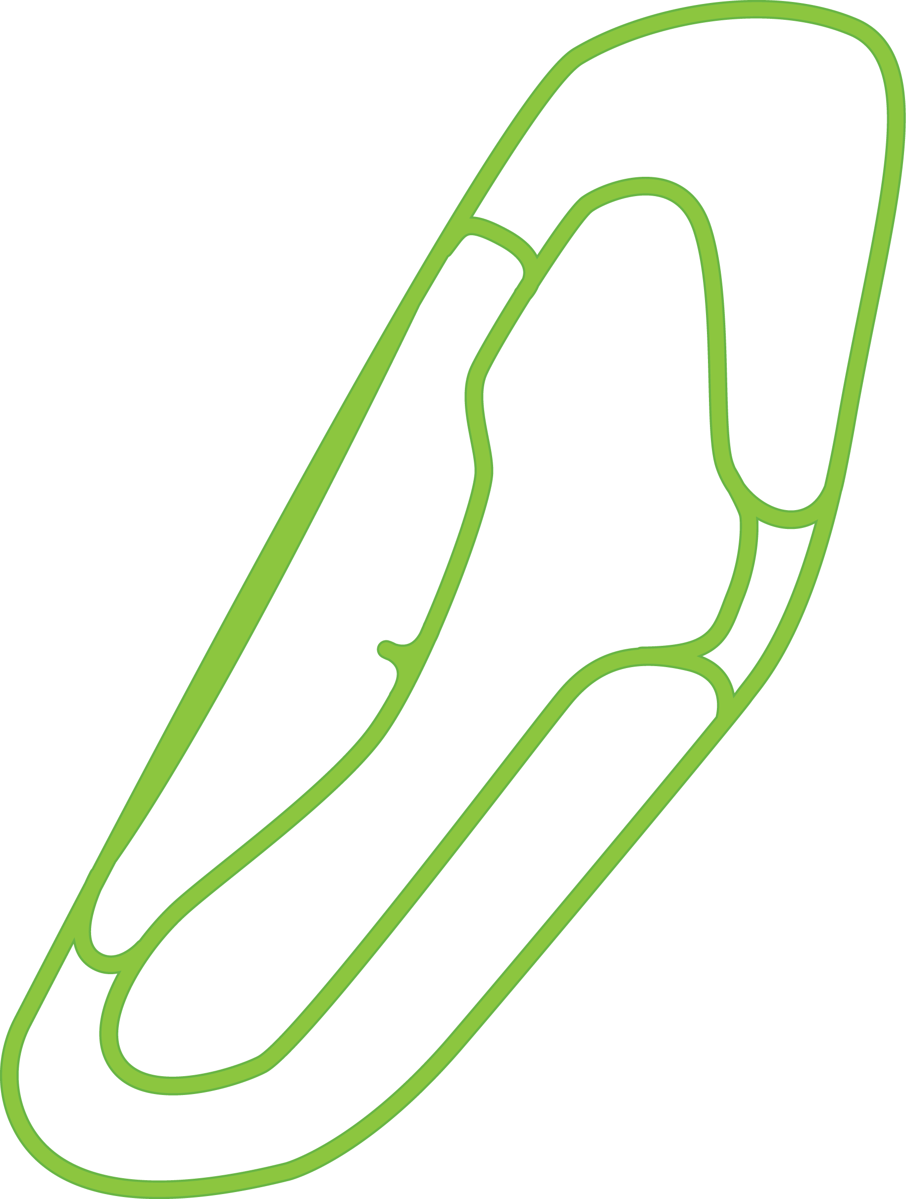
It broke under my heel.
So I rebuilt it from the loads up.
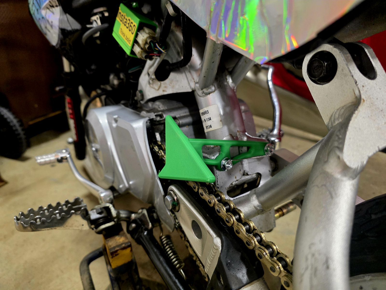
A printed heel guard keeps my boot off the chain on a 2001 Honda XR50. The first one snapped. I found the root cause, set up real loads for an adult rider, and let topology optimization find the load paths. Then FEA on every version until the pad stayed well clear of the chain.
- Bike
- 2001 Honda XR50, stock frame
- Rider
- 180 to 220 lb adult
- Design loads
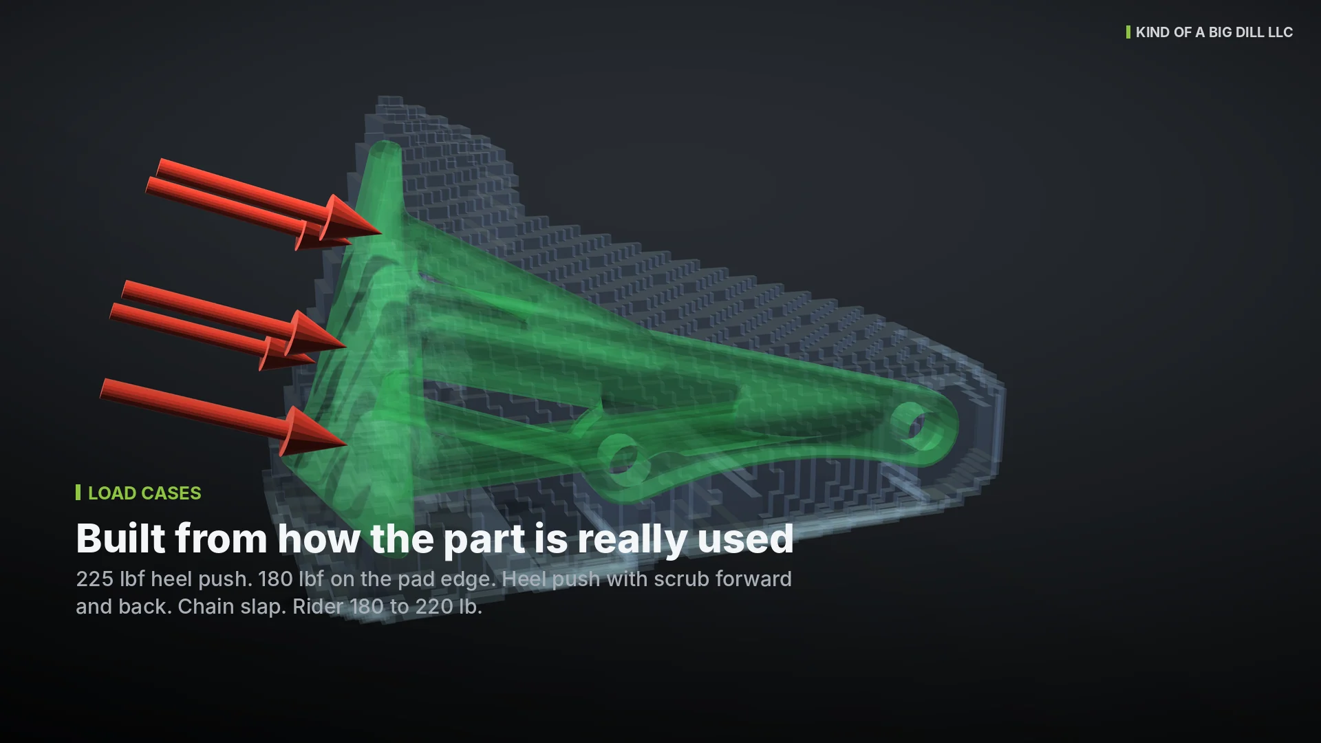
- 225 lbf heel push, 180 lbf on the edge
- Pad movement
- 3 to 8x less than the original (simulated)
- Weight
- 2.75 oz
- Status
- Test print on the printer
A broken part is the best design brief
The problem
My pit bike runs a printed heel guard that bolts to the frame tab and keeps my boot off the chain. The first one snapped at the arm and cracked at the bolt holes.
The approach
I treated it like a customer failure. Root cause first, then load cases from how the part is really used, keep-outs for the chain, bolts and frame, and topology optimization with an FEA check on every version.
The result
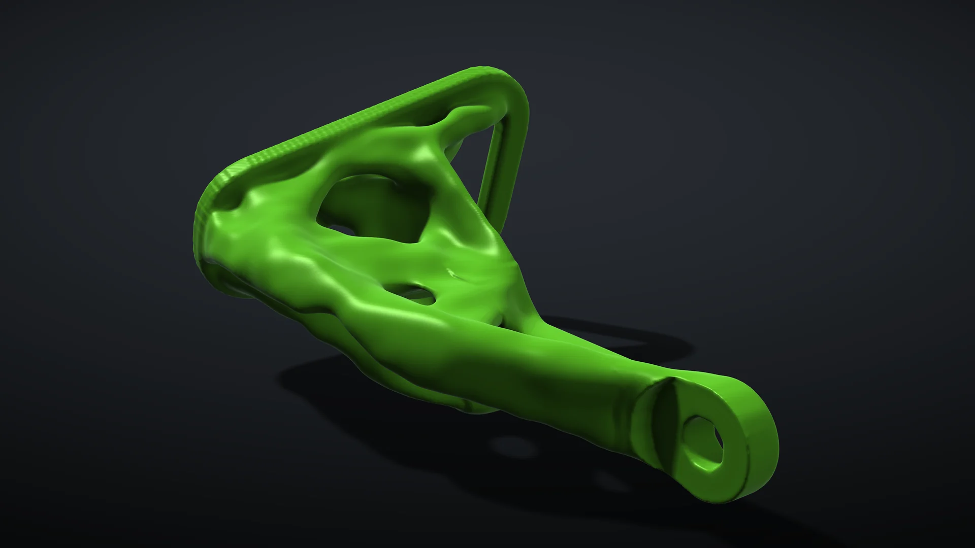
A bridged, open-skeleton guard with a clean mounting face. In simulation it moves 3 to 8 times less toward the chain under the same heel loads, for less than an ounce more.
Where it failed and why
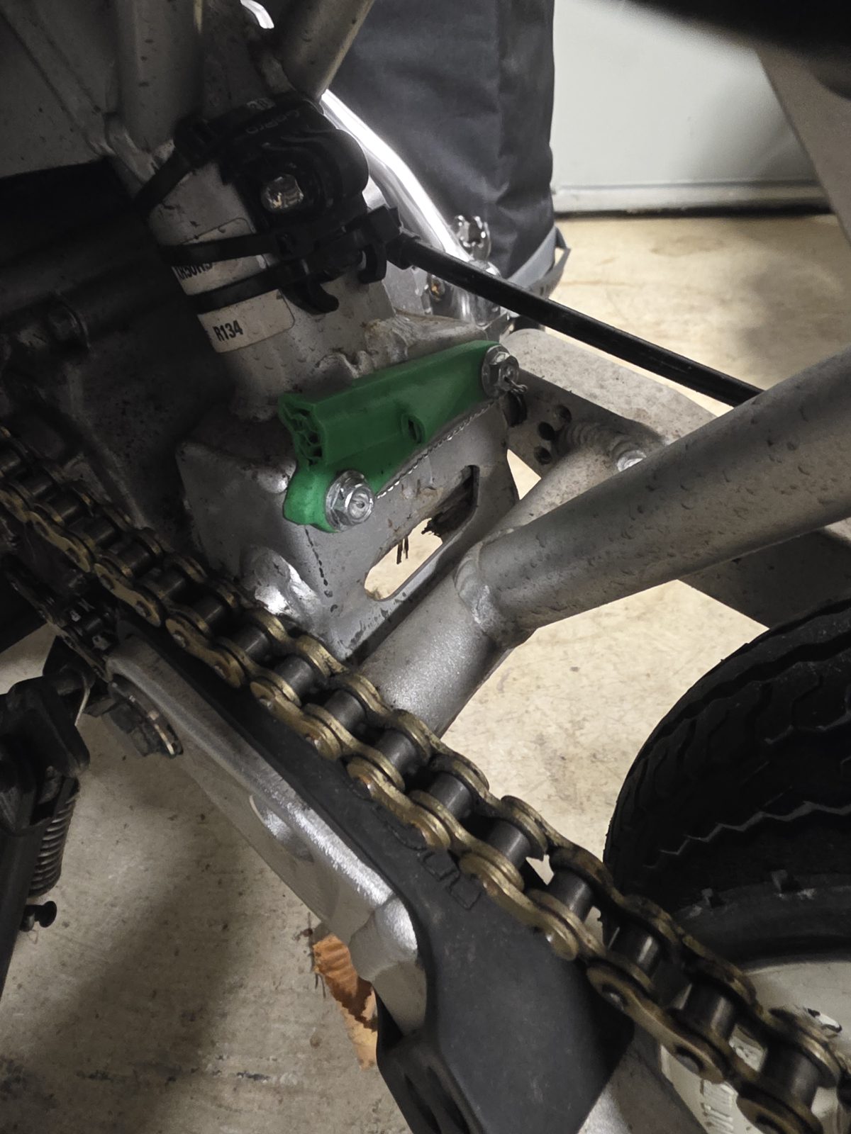
- 01A lightening window sat right where the bending load was highest.
- 02The print layers ran across that load instead of along it.
- 03The walls around the bolt holes were thin, so they cracked too.
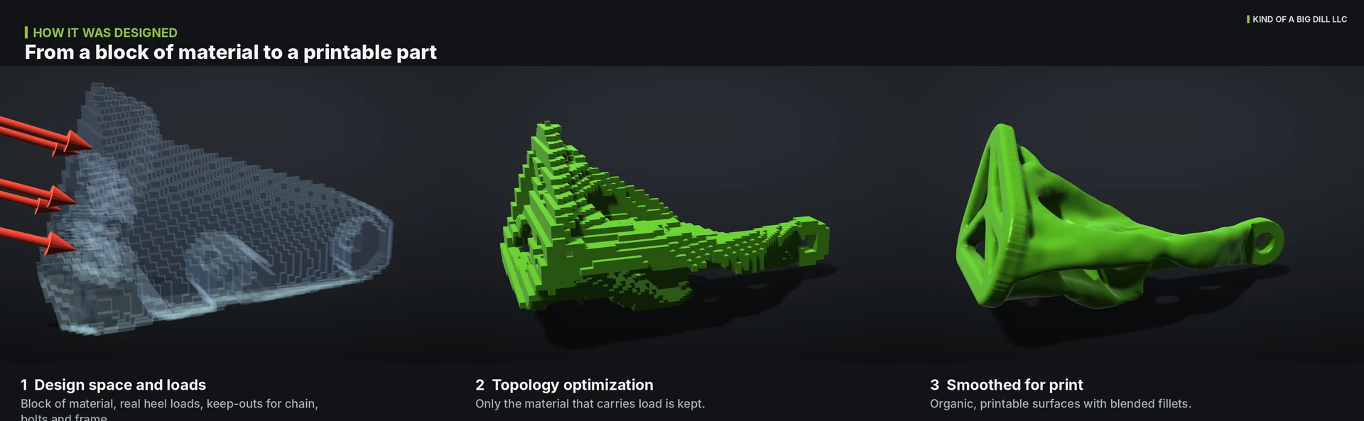
Real loads in, only the useful material out
Three features that do the work
Bridge between the bolts
Both bolt bosses are tied together, so the load spreads across the frame tab instead of tearing at one hole.
Open skeleton heel pad
The pad only has to stop a boot heel. A rounded rim and spokes do that with less material, and give the supports a place to land.
Clean mounting face
Nothing sits behind the frame side of the part, so it bolts flat to the tab with clear socket access to both bolts.
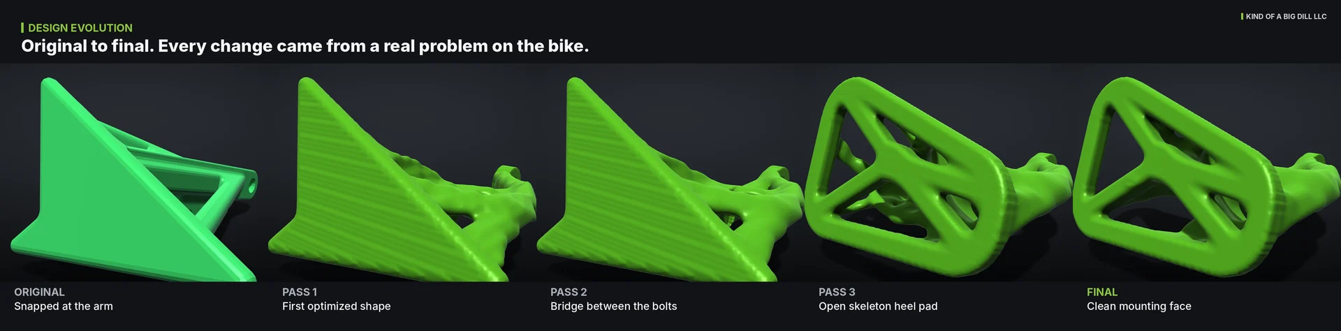
Original to final
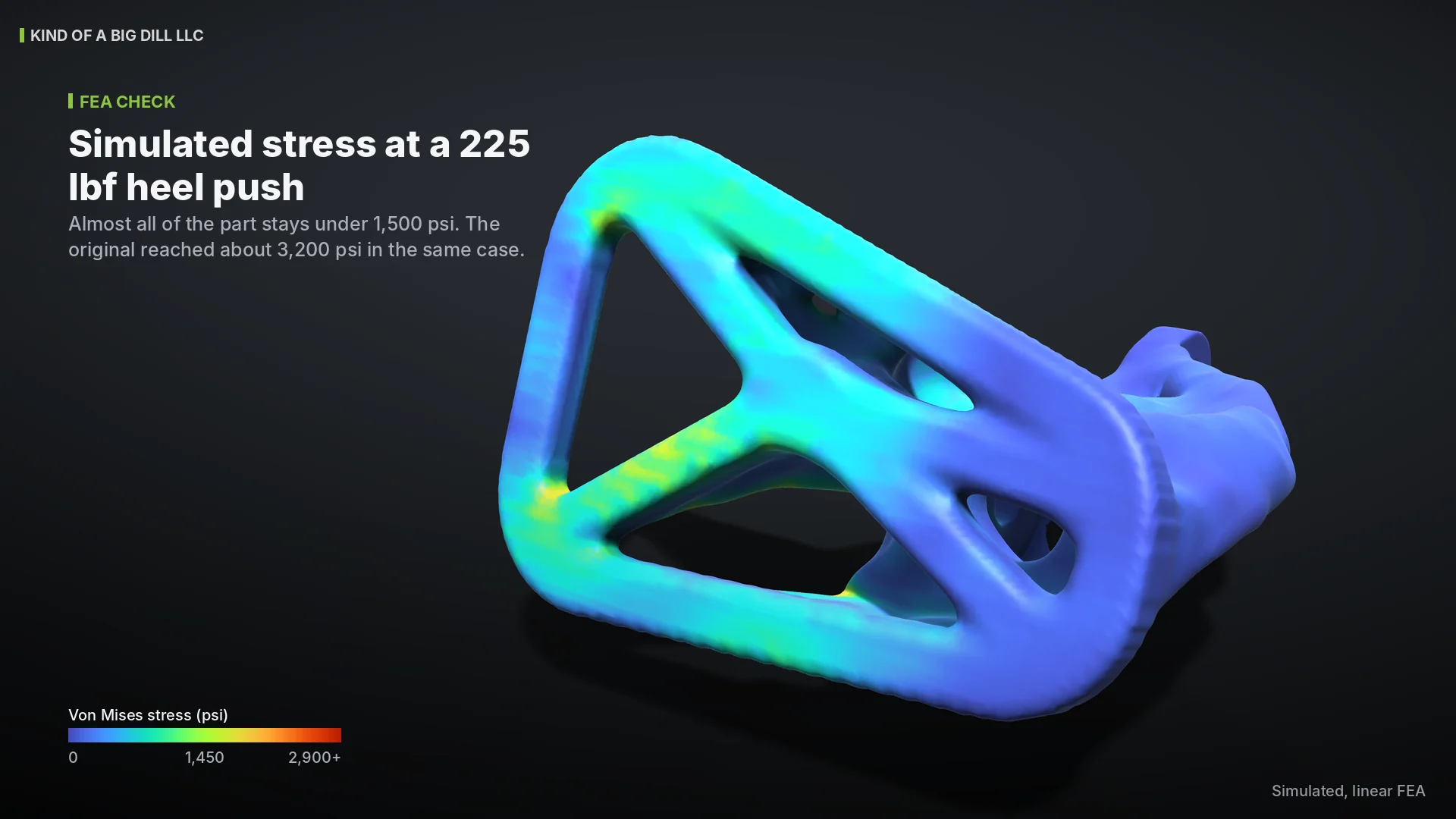
Stiffer where it counts
Pad movement toward the chain
| Load case | Original | New |
|---|---|---|
| Heel push, 225 lbf | 0.145 in | 0.043 in |
| Heel on outer edge, 180 lbf | 0.225 in | 0.028 in |
| Heel and scrub forward | 0.085 in | 0.017 in |
| Heel and scrub back | 0.218 in | 0.053 in |
- About 0.24 in of gap to the chain. The new part stays under 0.06 in in every case.
- Near-peak stress (99.5th percentile) drops from about 5,900 psi to about 1,600 psi in the worst case.
- 2.75 oz, up from 1.9 oz. Less than an ounce more for a part that is several times stiffer.
Linear FEA, same loads on both parts. Physical testing is in progress.
How it was designed
- 01
Failure review
Found the cause: a window in the highest bending zone, layers across the load and thin walls at the holes.
- 02
Real loads
Heel push, heel on the edge, scrub both ways and chain slap for a 180 to 220 lb rider.
- 03
Keep-outs
Chain in position with clearance, socket access to both bolts and a clean mounting face.
- 04
Topology optimization
Started from a block of design space and kept only what carries load toward the frame.
- 05
Iterations
Bridge, rounded pad, open skeleton, clean mount. Each change came from a real problem on the bike.
- 06
Smooth and check
Smoothed into a printable part and checked with FEA every time it changed.
Next up: the test print is on the printer. Fit check on the bike, a heel-stand proof test and a chain gap check come next, and the real-world results will land here.
What this means for your project
Root cause first, then a better part.
Send me the broken part or photos of it. I find out why it failed, build load cases from how it is really used, and redesign it so the fix holds up.
Lighter, stiffer and built to be made.
Topology optimization and FEA to set the shape, then a design that fits the process, whether that is a 3D print, a machined part or sheet metal. You get native CAD, STEP and drawings.
Got a part that keeps breaking?
Send me photos and what it has to do. I review every request myself and reply within 2 business days.
Start a project→